Building your own Infrared meter


This is a short instruction on how to build a simple yet useful infrared light meter. I found the instructions in the September 1987 issue of Darkroom Photography magazine in an article by Thomas F. Fuller.
Radio Shack project enclosure 5” x 2.5” x 2” #270-1803
0-15 Volt DC Panel Meter # 270-1754
Temporary push button switch
AA Battery
Medium size CdS cell
It is commonly held that CdS cells are best for visible light applications, which although true, does not mean that they can still be very useful for infrared applications. I found the following on Silonex's website: http://www.silonex.com/images/sfdraw/sf13d12f.gif It shows the spectral sensitivity of several different CdS cells. My guess is that the Radio Shack one is similar to the T5 500nm or the T9 560nm cell. These both have plenty of infrared sensitivity in the 700nm to 900nm range and beyond.
The basic principle of operation of the meter is that it uses a photoconductive CdS cell rather than a photovoltaic Silicon cell. Pressing the button activates the meter by allowing voltage to pass through the CdS photocell. The resistance of the photocell decreases with the quantity of light striking it. Therefore, the needle indicator shows higher readings with more light. The response to light energy is linear so that a doubling of the indicated reading, say from 2 to 4, indicates an increase of 1 stop of exposure. The gain of the meter is determined by the battery’s voltage. As a starting point, I’d recommend a AA battery. If you need more, use 2 AA’s or a 6 or 9 volt battery.
The electrical connections a re simple. You don’t have to use a soldering iron if you don’t want to. Just strip the wires, twist them tightly and wrap the connections with some electrical tape. Connect all of the pieces in series. The only polarity that is important is that of the battery. If it is in backwards, the needle on the meter will go backwards. Mount all of the pieces firmly inside the project case. You will have to drill a few holes. Drill a separate hole in the one of the walls of the case for the CdS cell to show through. Glue it in place firmly. Attach your choice of filter to the outside, covering the sensor hole. Adjust battery voltage to adjust the sensitivity for your typical IR photography scene. It would also be a good idea to add some sort of a light shade to limit the meter’s field of view.
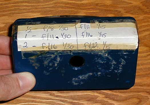
The meter shown in the photos is my original meter that I built in college. It’s messy from taping it in place and sometimes taping it shut when I lost the screws!
David Romano 2003